QoS — The 5G QoS Model¶
Learning objectives¶
After reading this page, you will be able to:
- Explain the Why (why QoS is needed) from the perspective of differentiation: if all traffic is treated equally, voice, emergency, video, and best-effort traffic compete and the user experience breaks down.
- Explain that the QoS Flow is the finest granularity of 5G QoS, that it is identified by a QFI (QoS Flow Identifier), and that a PDU Session contains one or more QoS Flows.
- Explain that the 5QI (5G QoS Identifier) is a standardized identifier of quality characteristics (priority, latency, packet error rate, etc.).
- Distinguish the difference between GBR / Non-GBR and the roles of Session-AMBR / UE-AMBR (guarantee vs. upper limit).
- Explain that the NG-RAN handles the QoS Flow ↔ DRB (Data Radio Bearer) mapping, and that the QFI is marked over N3 (GTP-U).
- Explain the separation of control (PCF→SMF decides) and enforcement (UPF applies rate control, NG-RAN applies scheduling), mapping it to each of the N7/N4/N2/N1/N3 interfaces.
- List the focal points for analyzing GTP-U(QFI) / NGAP(QoS profile) / PFCP(QER) in Wireshark.
- Contrast the differences between 4G (EPC) QoS (per-EPS-bearer / QCI / APN-AMBR) and 5G QoS (per-QoS-Flow / 5QI / Session-AMBR).
Prerequisites¶
It will go more smoothly if you first understand the following. If you haven't yet, start from the home.
- Understanding the PDU Session (QoS is applied inside a PDU Session; a QoS Flow is contained within a PDU Session) → PDU Session Establishment
- The basics of N4 / PFCP (the SMF sets forwarding and QoS rules such as PDR/FAR/QER on the UPF) → N4
- The role of the PCF (it provides policy/QoS as PCC Rules) → PCF
- The roles of the SMF / UPF (the SMF decides QoS, the UPF applies forwarding and QoS) → SMF / UPF
What you'll learn in this chapter¶
This chapter focuses narrowly on the 5G QoS model. It thematizes the QoS skeleton of the QoS Flow (finest granularity), 5QI, GBR/Non-GBR, and AMBR, and which NFs and interfaces perform its control (decision) and enforcement (execution).
- The establishment of a QoS Flow itself happens as part of PDU Session Establishment. This chapter takes the structure of the QoS model as its theme and directs you to pdu-session for the PDU Session establishment procedure itself.
- The details of the PFCP rules (the specifics of PDR/FAR/QER/URR) are directed to N4. This chapter treats the positioning of the QER (QoS Enforcement Rule) conceptually.
- The radio-side details (radio resource allocation and scheduling algorithms for the DRB) are kept conceptual; the details are out of scope (radio side, implementation-dependent).
- Network Slicing is the theme of the Network Slicing chapter; this chapter only mentions it to the extent it is relevant (the details of S-NSSAI and slice selection are there).
Why — why QoS is needed¶
Let's start with the Why (why it's needed). In a mobile network, traffic of completely different natures flows simultaneously. Voice calls are sensitive to latency — even a slight delay or packet loss makes the call cut out. Emergency calls must be given top priority and delivered reliably. Video streaming needs a certain bandwidth but can tolerate some latency. Email and background updates are fine even if slow (best-effort).
If all of these are treated equally, then during congestion a flood of video and downloads eats up the bandwidth, and the user experience breaks down — voice cuts out and emergency calls don't get through. So the network needs a mechanism to distinguish (differentiate) traffic by its nature, to prioritize what should be prioritized, and to guarantee bandwidth for what needs it. This is QoS (Quality of Service).
Analogy: priority lanes on a highway and an ambulance
QoS is similar to highway lane design. If you cram all vehicles into a single lane, both the ambulance and the commuter get caught in traffic. So you clear a dedicated lane for the ambulance (emergency call) (top priority, guaranteed), provide a priority lane for buses (voice) (low latency, priority), and let general vehicles (video, email) flow in the normal lane according to traffic volume. 5G QoS performs this "lane separation" in units called QoS Flows, specifies which lane (quality) to use with a number called the 5QI, and uses guaranteed lanes (GBR) and shared lanes (Non-GBR) accordingly.
Overview¶
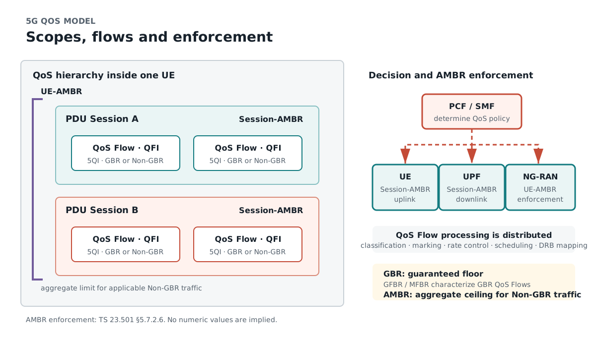
The 5G QoS model takes the QoS Flow as its finest granularity. Within one PDU Session (the pipe going from the UE out to the DN), there are one or more QoS Flows, and each QoS Flow is identified by a QFI (QoS Flow Identifier). Packets belonging to the same QoS Flow receive the same QoS treatment (priority, latency, rate, etc.).
The quality of each QoS Flow is specified by the following elements.
| Element | What it represents | Positioning |
|---|---|---|
| QFI | The identifier of a QoS Flow | The number that distinguishes a QoS Flow. Marked over N3 (GTP-U) |
| 5QI | A standard number for quality characteristics (priority/latency/error rate, etc.) | A "quality menu number" that indicates what kind of quality it is with a single number. The standardized values are in TS 23.501 §5.7 (section number to be confirmed) |
| GBR / Non-GBR | Whether bandwidth is guaranteed | GBR = guaranteed (has GFBR/MFBR), Non-GBR = not guaranteed (shared) |
| Session-AMBR | The total bandwidth cap per PDU Session | The cap on the total of that PDU Session's Non-GBR flows (to be confirmed: scope of application) |
| UE-AMBR | The total bandwidth cap per UE | The cap on the total Non-GBR of that whole UE (to be confirmed: scope of application) |
The key point of 5G QoS is that the "one who decides" and the "one who enforces" are separated. The PCF/SMF decide QoS (control plane), and the UPF performs rate control and marking, while the NG-RAN performs radio scheduling (user plane).
flowchart LR
    PCF["PCF
(policy/PCC Rule)"] -- "N7" --> SMF["SMF
(QoS decision)"]
    SMF -- "N4: QER/PDR" --> UPF["UPF
(rate control/marking)"]
    SMF -- "N2(via AMF): QoS profile" --> RAN["NG-RAN
(QoS Flow→DRB)"]
    SMF -- "N1(NAS): QoS rules" --> UE["UE
(UL classification)"]
    RAN == "N3: QFI marking" ==> UPF

    classDef ctrl fill:#eef,stroke:#66a,stroke-width:1px;
    classDef data fill:#efe,stroke:#3a3,stroke-width:2px;
    class PCF,SMF ctrl;
    class UPF,RAN data;
Basic Concept — a beginner-friendly explanation¶
To understand 5G QoS, there are three keywords to nail down.
1. What a QoS Flow is (a "grouping" that aligns quality)¶
A QoS Flow is a grouping of traffic to which the same quality (QoS) is applied within a PDU Session. In 5G, this QoS Flow is the finest granularity of QoS, and it is identified by a number called the QFI (QoS Flow Identifier).
For example, within a single PDU Session (an internet connection), you can have a "QoS Flow for voice (low latency, priority)" and a "QoS Flow for general data (best-effort)" coexist. In the highway analogy, it's the image of drawing purpose-specific lanes (QoS Flows) within a single road (PDU Session).
Then, each core-side QoS Flow (QFI) is mapped by the NG-RAN to a DRB (Data Radio Bearer) on the radio side. The diagram below shows the containment/correspondence relationship of "PDU Session > QoS Flow > DRB." Multiple QoS Flows can also be bundled onto a single DRB (radio side, implementation-dependent); this "QoS Flow↔DRB mapping" is the point that became more flexible than 4G's bearer-integrated approach.
flowchart LR
    subgraph CORE["Core side (per QoS Flow)"]
        direction TB
        PDU["PDU Session"]
        QF1["QoS Flow A
(QFI=1, 5QI=1 voice/GBR)"]
        QF2["QoS Flow B
(QFI=2, 5QI=9 data/Non-GBR)"]
        QF3["QoS Flow C
(QFI=3, 5QI=9 data/Non-GBR)"]
        PDU --> QF1
        PDU --> QF2
        PDU --> QF3
    end
    subgraph RAN["Radio side (per DRB; NG-RAN maps)"]
        direction TB
        DRB1["DRB #1
(for voice)"]
        DRB2["DRB #2
(for data, bundled)"]
    end
    QF1 -->|"1:1"| DRB1
    QF2 -->|"bundle"| DRB2
    QF3 -->|"bundle"| DRB2

    classDef gbr fill:#fde,stroke:#c69;
    classDef ngbr fill:#eef,stroke:#66a;
    class QF1 gbr;
    class QF2,QF3 ngbr;
How to read the diagram
On the core side, the QoS Flow (QFI) is the finest granularity, and multiple QoS Flows coexist within one PDU Session. On the radio side, the NG-RAN maps each QoS Flow to a DRB. In the diagram, voice (QFI=1) is put on a dedicated DRB, and the two data flows (QFI=2,3) are bundled onto one DRB. This mapping is decided by the NG-RAN, and the values (QFI/5QI/number of DRBs) are just one example (implementation-dependent). The QFI is attached to packets over N3 (GTP-U), and serves as the clue by which the NG-RAN identifies the corresponding DRB.
2. What a 5QI is (the "menu number" of quality)¶
A 5QI (5G QoS Identifier) represents a set of quality characteristics — latency (Packet Delay Budget), packet error rate (Packet Error Rate), priority (Priority Level) — with a single standardized number. Like a menu number at a restaurant, saying "5QI = number ◯" fixes that combination of quality characteristics.
The standardized 5QI values and their characteristics are defined in the standardized 5QI table in 3GPP TS 23.501 §5.7 (section number to be confirmed). Representative values for voice, conversational video, best-effort, and so on are specified, but this page does not assert the concrete values of individual 5QIs, latency values, or error rates (the values are to be confirmed against TS 23.501 §5.7; our policy is not to write fictitious values). It is a concept corresponding to the 4G QCI.
3. GBR・Non-GBR and AMBR (guarantee and upper limit)¶
QoS Flows are divided into two kinds by whether bandwidth is guaranteed.
- GBR (Guaranteed Bit Rate) — a QoS Flow that guarantees a certain bandwidth. For traffic that does not work without sufficient bandwidth, such as voice or conversational video. It has a guaranteed rate GFBR (Guaranteed Flow Bit Rate) and a maximum rate MFBR (Maximum Flow Bit Rate).
- Non-GBR — a QoS Flow that does not guarantee bandwidth. For best-effort data, its quality is handled mainly on a 5QI basis, and it is shared during congestion.
And what defines the upper limit on the total amount of bandwidth is the AMBR (Aggregate Maximum Bit Rate).
- Session-AMBR — the bandwidth cap on the total Non-GBR traffic per single PDU Session.
- UE-AMBR — the bandwidth cap on the total Non-GBR traffic across a single UE as a whole.
GBR is the 'floor (guarantee),' AMBR is the 'ceiling (cap)'
Whereas GBR is a floor (guarantee) meaning "we'll put out at least this much," AMBR is a ceiling (cap) meaning "we won't put out any more than this." A GBR flow has an individual guarantee (GFBR) and cap (MFBR), while the group of Non-GBR flows has an overall ceiling (Session-AMBR / UE-AMBR). The details of the scope of application and the combination of the two are to be confirmed against TS 23.501 §5.7.
The diagram below expresses this "floor" and "ceiling" relationship as bandwidth height. A GBR flow has bandwidth from GFBR (the floor) up to MFBR (the ceiling), and the network reserves the GFBR portion. A group of Non-GBR flows is not guaranteed bandwidth and is shared, as a whole, under the ceiling of the Session-AMBR (and further, across the whole UE, the UE-AMBR).
flowchart TB
    subgraph GBRflow["GBR flow (e.g., voice 5QI=1)"]
        direction TB
        MFBR["── MFBR (ceiling: no more than this) ──"]
        GAP["(GFBR〜MFBR: used if available)"]
        GFBR["── GFBR (floor: minimum guaranteed, NW reserves) ──"]
        MFBR --- GAP --- GFBR
    end
    subgraph NGBRflow["Group of Non-GBR flows (e.g., Web/email)"]
        direction TB
        AMBR["── Session-AMBR (ceiling: total cap) ──"]
        SHARE["(no guarantee; shared during congestion / best-effort)"]
        FLOOR["(no floor: no bandwidth guarantee)"]
        AMBR --- SHARE --- FLOOR
    end

    classDef ceil fill:#fde,stroke:#c69,stroke-width:1px;
    classDef floor fill:#dfd,stroke:#6a6,stroke-width:1px;
    class MFBR,AMBR ceil;
    class GFBR floor;
How to read the diagram
The upper GBR flow has its GFBR (floor) guaranteed by the network and can go up to MFBR (ceiling). Having a floor is the characteristic of GBR. The lower group of Non-GBR flows has no floor (guarantee) and is shared under the Session-AMBR (ceiling). The key point is that the roles of GBR's "floor" and AMBR's "ceiling" are opposite. Across the whole UE, a further higher ceiling, the UE-AMBR, applies.
Architecture¶
Here are the elements involved in the 5G QoS model and the interfaces that connect them. The star of this chapter is the point that the control plane (deciding QoS: PCF→SMF) and the user plane (applying QoS: UPF / NG-RAN) are separated.
flowchart LR
    subgraph CP["Control Plane (QoS decision)"]
      PCF["PCF
(PCC Rule)"]
      SMF["SMF
(QoS decision)"]
      AMF["AMF
(N2 transport relay)"]
    end
    subgraph UP["User Plane (QoS enforcement)"]
      UPF["UPF
(QER: rate/marking)"]
      RAN["NG-RAN / gNB
(QoS Flow→DRB)"]
    end

    PCF -- "N7 (Npcf_SMPolicyControl): PCC Rule" --> SMF
    SMF -- "N4 (PFCP): QER/PDR" --> UPF
    SMF -- "N1 (NAS): QoS rules" --> UE(("UE
(UL classification)"))
    SMF -- "N2 SM info: QoS profile" --> AMF
    AMF -- "N2 (NGAP): QoS profile" --> RAN
    RAN == "N3 (GTP-U): QFI marking" ==> UPF
    UPF == "N6" ==> DN[(Data Network)]

    classDef core fill:#efe,stroke:#3a3,stroke-width:2px;
    class PCF,SMF,UPF core;
The roles of each element are as follows.
- PCF — the source of policy. It creates PCC Rules (Policy and Charging Control Rules) according to the subscriber and application, and passes the QoS parameters (5QI, GBR/Non-GBR, AMBR, etc.) to the SMF over N7 (in a dynamic-PCC configuration).
- SMF — the decider of QoS. Based on the PCF's policy (or default values), it decides the QoS of each QoS Flow and distributes the QER/PDR to the UPF over N4, the QoS profile to the NG-RAN over N2 (via the AMF), and the QoS rules to the UE over N1 (NAS).
- UPF — the enforcer of QoS on the user plane. Following the QER (QoS Enforcement Rule) set by the SMF, it performs rate control (applying caps such as Session-AMBR) and DL-side QFI marking.
- AMF — the transport relay for N2. It relays the N2 SM info containing the QoS profile generated by the SMF to the NG-RAN (it does not decide the QoS content).
- NG-RAN / gNB — the QoS enforcer on the radio side. It maps the core-side (QoS Flow, QFI) to the radio-side DRB (Data Radio Bearer) and performs radio scheduling. It is not a core NF (it is on the radio access side).
For details on the interfaces, see the Interface Dictionary.
Network Function¶
Here are the roles of the main NFs involved in 5G QoS. The NG-RAN is on the radio access side and is not a core NF (this table is from a core viewpoint, with the NG-RAN listed alongside as the party responsible for the QoS Flow↔DRB mapping).
| NF | Role in this context | Information held/obtained | Main APIs/procedures | Impact on failure |
|---|---|---|---|---|
| PCF | Provides QoS/charging policy (PCC Rules). Decides 5QI, GBR/Non-GBR, AMBR, etc. and passes them to the SMF | PCC Rules, authorized QoS, subscriber policy | Npcf_SMPolicyControl (N7, TS 29.512) | Policy not applied (may continue with the SMF's default QoS = configuration-dependent) |
| SMF | The decision-maker of QoS. Finalizes the QoS per QoS Flow and distributes the QER/QoS profile/QoS rules in each direction | QoS Flow (QFI/5QI), GBR/AMBR, QoS info for UPF/NG-RAN | Nsmf_PDUSession (provided), N4 (PFCP), Npcf (consumed) | QoS is not distributed and quality control does not work |
| UPF | QoS enforcement on the user plane. Rate control via QER, DL-side QFI marking | PDR/FAR/QER, caps such as Session-AMBR, QFI | PFCP (N4, TS 29.244. QER configuration) | Rate control/marking not performed, so QoS breaks down |
| AMF | Transport relay for N2. Relays the N2 SM info containing the QoS profile to the NG-RAN (does not decide the QoS content) | N2 SM info (containing the QoS profile) | NGAP (N2 transport), Namf_Communication | The QoS profile doesn't reach the NG-RAN, so radio-side QoS is not configured |
| NG-RAN / gNB (not a core NF) | (QoS Flow, QFI) ↔ DRB mapping, radio scheduling. For UL, sets the QFI in the N3 PDU Session Container based on the QFI the UE put in the SDAP header if a UL SDAP header is configured, otherwise on the DRB correspondence (TS 38.415, TS 37.324; clause numbers to be confirmed) | QoS profile, DRB configuration, QFI↔DRB correspondence | NGAP (receives QoS profile), RRC (DRB setup) | QoS is not applied on the radio side, so priority control does not work |
Interface / Protocol¶
Here are the main interfaces and protocols used in this context. We organize how QoS information flows over which segments and in what form.
| Interface | Protocol | Transport | Segment | Use in this context |
|---|---|---|---|---|
| N7 | SBI (HTTP/2, TLS, JSON) | TCP/TLS | PCF ⇔ SMF | Fetches PCC Rules (5QI/GBR/AMBR, etc.) via Npcf_SMPolicyControl (TS 29.512) |
| N4 | PFCP | UDP (port 8805) | SMF ⇔ UPF | Sets QER/PDR on the UPF to instruct rate control and marking (TS 29.244) |
| N2 | NGAP | SCTP (port 38412) | gNB ⇔ AMF | Transports the QoS profile to the NG-RAN (via the AMF; TS 38.413) |
| N1 | NAS (5GSM) | (tunneled over NGAP/N2) | UE ⇔ AMF | Distributes QoS rules to the UE (for classifying UL traffic into QoS Flows; TS 24.501) |
| N3 | GTP-U | UDP (port 2152) | gNB ⇔ UPF | Marks the QFI on user-plane packets (GTP-U is TS 29.281 / the PDU Session Container that carries the QFI is TS 38.415) |
The difference in direction between QoS profile and QoS rules
The QoS profile is generated by the SMF and is for the NG-RAN (N2) — the radio side uses it for DRB mapping and scheduling. The QoS rules are generated by the SMF and are for the UE (N1 NAS) — the UE uses them to classify which QoS Flow to carry UL (uplink) traffic on. The QER is for the UPF (N4) — it performs rate control and DL marking. The three are in the relationship of "distributing the same QoS decision to each enforcing party: the NG-RAN, the UE, and the UPF." The details of operation names and IE names are version/implementation-dependent, and some are to be confirmed.
For details on the protocols, see the Protocol Dictionary, and for the interface list, see the Interface Dictionary.
Procedure — Call Flow¶
This is the heart of this page. The control flow accompanying the establishment/modification of a QoS Flow is shown as a Mermaid sequenceDiagram. The basis is TS 23.502 (QoS configuration within the PDU Session establishment/modification procedures), TS 23.501 §5.7 (the QoS model, section number to be confirmed), TS 29.512 (Npcf_SMPolicyControl), TS 29.244 (PFCP QER), and TS 38.413 (NGAP QoS profile). Since a QoS Flow is in many cases established as part of PDU Session Establishment, here we focus on the distribution of the QoS configuration (for the overall PDU Session establishment procedure, see pdu-session).
Precondition: QoS is configured in the context of PDU Session establishment/modification
The establishment of a QoS Flow is not an independent procedure; it happens within PDU Session Establishment or PDU Session Modification. This diagram extracts the QoS decision → distribution to the UPF/NG-RAN/UE part of it. The operation names and ordering conform to TS 23.502, but the details are version/implementation-dependent, and some are to be confirmed.
sequenceDiagram
    autonumber
    participant UE
    participant RAN as NG-RAN / gNB
    participant AMF
    participant SMF
    participant PCF
    participant UPF

    Note over SMF,PCF: A QoS decision becomes necessary on the trigger of PDU Session establishment/modification
    opt Dynamic PCC (PCF interaction, conditional)
        SMF->>PCF: Npcf_SMPolicyControl (PCC Rule request)
        PCF-->>SMF: PCC Rule (5QI, GBR/Non-GBR, AMBR, etc.)
        Note right of PCF: N7 / TS 29.512
    end
    Note over SMF: Decide the QoS per QoS Flow
(QFI assignment, 5QI, GBR/AMBR)

    SMF->>UPF: PFCP Session Establishment/Modification (QER/PDR)
    Note right of SMF: N4 / TS 29.244. Instructs rate control and DL QFI marking
    UPF-->>SMF: PFCP Response

    SMF->>AMF: N2 SM info (QoS profile) + N1 (QoS rules)
    Note right of SMF: Namf_Communication_N1N2MessageTransfer
    AMF->>RAN: Deliver the QoS profile carried in NGAP
    Note right of AMF: N2 / TS 38.413
    RAN->>RAN: Decide the QoS Flow(QFI) ↔ DRB mapping
    RAN->>UE: DRB setup via RRC + deliver N1 (QoS rules)
    Note over RAN,UE: Radio-side DRB setup (outline/out of scope)

    Note over UE,UPF: Subsequent data: QFI marking over N3
DL: the UPF sets it on N3
UL: the UE classifies via QoS rules (sets the QFI if a SDAP header is configured), the gNB sets it on N3
Step-by-step explanation (numbers correspond to the diagram above)¶
1-2. (conditional) SMF↔PCF: In a dynamic-PCC configuration, the SMF fetches the PCC Rule with Npcf_SMPolicyControl (N7). The PCC Rule includes QoS parameters such as 5QI, the GBR/Non-GBR distinction, and AMBR (TS 29.512). In a PCF-less (static PCC) configuration, the SMF's default QoS is used (configuration-dependent).
3. (inside the SMF) QoS decision: The SMF assigns a QFI per QoS Flow and finalizes the 5QI and GBR/AMBR.
4-5. SMF→UPF: With PFCP Session Establishment/Modification (N4), it sets the QER (QoS Enforcement Rule) and PDR on the UPF. The QER instructs rate control (caps such as Session-AMBR) and DL-side QFI marking (TS 29.244). For the PFCP rule details, see N4.
6-7. SMF→AMF→NG-RAN: The SMF distributes the N2 SM info containing the QoS profile and the QoS rules for the UE (N1) via the AMF. The AMF carries the QoS profile in NGAP to the NG-RAN (N2 transport relay, TS 38.413).
8. NG-RAN's DRB mapping: The NG-RAN decides the (QoS Flow, QFI) ↔ DRB correspondence. Multiple QoS Flows may be bundled onto one DRB (radio side, implementation-dependent).
9. NG-RAN⇔UE (radio side, outline/out of scope): The NG-RAN sets up the DRB via RRC and delivers the bundled QoS rules to the UE.
10. QFI marking during data transfer: For subsequent real data, the UPF marks the QFI over N3 (GTP-U) for DL according to the QoS Flow, and the NG-RAN carries it onto the corresponding DRB. For UL, the UE classifies traffic into QoS Flows based on the QoS rules and, on DRBs for which a UL SDAP header is configured by RRC, sends it with the QFI in the radio-side SDAP header (TS 37.324 §6.2.2.3, TS 38.331 sdap-HeaderUL; to be confirmed). It is the gNB that sets the UL QFI in the PDU Session Container on N3 (GTP-U) (TS 38.415; clause numbers to be confirmed).
The procedure is embedded within PDU Session establishment/modification
The diagram above extracts the skeleton of QoS distribution. In practice, it is woven into the Call Flow of PDU Session Establishment and integrated with the two N4 stages of Establishment→Modification and the N2 resource setup. The message ordering, operation names, and some IEs are version/implementation-dependent and to be confirmed.
References: TS 23.501 §5.7 (the QoS model, section number to be confirmed), TS 23.502 (PDU Session procedures with QoS configuration), TS 29.512 (Npcf_SMPolicyControl), TS 29.244 (PFCP QER), TS 38.413 (NGAP QoS profile).
Signal Flow¶
We organize the main "containers of information" that carry QoS information, by direction. Some IE names and operation names are version/implementation-dependent, so they are to be confirmed.
| Information | Protocol | Source→Dest | Purpose | Main contents (some to be confirmed) |
|---|---|---|---|---|
| PCC Rule | SBI (Npcf_SMPolicyControl) | PCF→SMF | Provide QoS/charging policy | 5QI, GBR/Non-GBR distinction, GFBR/MFBR, AMBR, flow descriptors, etc. |
| QER / PDR | PFCP | SMF→UPF | Instruct QoS enforcement on the UPF | QER (rate cap = Session-AMBR, etc., DL QFI marking), PDR (detection conditions), etc. |
| QoS profile | NGAP (N2 SM info) | SMF→(AMF→)NG-RAN | Configure radio-side QoS | 5QI, ARP, GBR parameters (GFBR/MFBR), QFI, etc. (IE names to be confirmed) |
| QoS rules | NAS (5GSM) | SMF→(AMF→)UE | The UE's UL classification rules | QFI, packet filters (UL traffic→QoS Flow correspondence), priority, etc. |
| QFI marking | GTP-U (N3) | UPF/NG-RAN | Identify the QoS Flow on the data plane | The QFI inside the GTP-U extension header (PDU Session Container, IE name to be confirmed) |
Distributing 'one QoS decision' to each enforcing party
The table above represents the flow of distributing the single QoS decision made by the SMF, in each form, to the three enforcing parties: the UPF (QER), the NG-RAN (QoS profile), and the UE (QoS rules). On the data plane, the QFI becomes the common "tag" and indicates over N3 which QoS Flow a packet belongs to. For the details of each IE and its reference spec, see the Message Dictionary.
State Machine¶
Here is the (conceptual) lifecycle of a QoS Flow. A QoS Flow is subordinate to the PDU Session and does not have a heavy independent state machine (it is tied to the PDU Session's state). The basis is TS 23.501 §5.7 (the QoS model, section number to be confirmed).
stateDiagram-v2
    [*] --> NonExistent: Not yet established within the PDU Session
    NonExistent --> Established: QoS Flow establishment (QFI assignment, distribution of QoS profile/QER/QoS rules)
    Established --> Established: QoS Modification (5QI/GBR/AMBR change, QFI preserved)
    Established --> Released: QoS Flow release / PDU Session release
    Released --> [*]
- NonExistent — a state in which that QoS Flow does not yet exist within the PDU Session.
- Established — a state in which a QFI has been assigned, the QoS profile (NG-RAN), QER (UPF), and QoS rules (UE) have been distributed, it is mapped to the corresponding DRB, and data flows.
- Released — a state in which the QoS Flow has been released, or the PDU Session it belongs to has been released.
A QoS Flow's state is subordinate to the PDU Session
A QoS Flow is an internal element of the PDU Session, and if the PDU Session becomes inactive (CM-IDLE, etc.), that QoS Flow's user plane is also deactivated. Since a strict standalone state definition of a QoS Flow is not treated extensively as an explicit state machine in the 3GPP spec, the diagram above is a conceptual representation for understanding (the state names are to be confirmed).
Packet Analysis (Wireshark)¶
Here are the focal points when analyzing 5G QoS with Wireshark. Because QoS spans multiple segments, you use different filters per segment.
Main display filters¶
| Filter | Meaning | Segment to observe |
|---|---|---|
gtp |
GTP-U (N3. Includes QFI marking) | N3 |
ngap |
NGAP (PDU Session Resource setup containing the QoS profile) | N2 |
pfcp |
PFCP (N4. Session Establishment/Modification containing QER configuration) | N4 |
nas-5gs.sm |
5GS NAS SM (Accept, etc., containing QoS rules) | N1 |
IE names, values, and field positions are environment-dependent, to be confirmed
The header position of the QFI, the QoS profile IE name in ngap, and the QER field name in pfcp are based on 3GPP assignments, but the display and matching method may differ depending on the Wireshark version / dissector implementation. This page does not assert fictitious numbers or IE names. Treat the concrete field names and values as to be confirmed; on real equipment, checking via the GUI's protocol hierarchy view is the surest approach.
Points to look at when decoding (main IEs)¶
- The QFI of GTP-U (N3) — the QFI is inside the GTP-U extension header (PDU Session Container, IE name to be confirmed) and indicates which QoS Flow that packet belongs to. The UPF sets it for DL, and the gNB sets it for UL (TS 38.415). The UE sets the QFI not on N3 but in the radio-side SDAP header (when a UL SDAP header is configured for the DRB; TS 37.324). Clause numbers are to be confirmed.
- The QoS profile of NGAP (N2) — within the PDU Session Resource setup message, the 5QI, ARP, and GBR parameters (GFBR/MFBR), etc., of each QoS Flow are carried (IE names to be confirmed).
- The Create QER of PFCP (N4) — the QER within Session Establishment/Modification contains the rate cap (Session-AMBR, etc.) and the DL-side QFI marking instruction (field names to be confirmed).
Where the QFI appears¶
The QoS "tag," the QFI, appears in a different container per segment.
N3 (GTP-U): the QFI inside the GTP-U header extension (PDU Session Container)
N2 (NGAP) : inside the QoS profile (per QoS Flow, the QFI and 5QI/GBR, etc.)
N1 (NAS)  : inside the QoS rules (references the QFI as the correspondence table for UL classification)
Actual pcaps are environment-dependent (implementation-dependent)
The filters and IE names on this page are guidelines for analysis. Since N3 (GTP-U) / N4 (PFCP) are core-internal segments, they may not be visible depending on the capture point. If you set up a PDU Session with a configured 5QI/QoS Flow on an Open5GS or free5GC testbed and run traffic, you can actually observe the N3 QFI marking and the N4 QER (implementation-dependent).
Configuration¶
Here are the structure-level essentials of the configuration needed to make 5G QoS work. Concrete values and vendor-specific items (Cisco, etc.) are implementation-dependent, and we do not write fictitious values here.
QoS configuration viewpoint (SMF/PCF side)¶
- Default 5QI / QFI — in a PCF-less (static PCC) configuration, the default 5QI and corresponding QFI assigned per DNN. For standardized 5QI values, refer to the representative values in TS 23.501 §5.7 (section number to be confirmed), and do not use fictitious values.
- Specifying GBR / Non-GBR — configure per QoS Flow whether it is guaranteed (GBR: GFBR/MFBR) or shared (Non-GBR).
- AMBR — the cap values of Session-AMBR (per PDU Session) and UE-AMBR (per UE, typically derived from subscriber data).
- PCC Rule (dynamic PCC) — when using a PCF, define PCC Rules (5QI, GBR, AMBR, flow descriptors) according to the application/subscriber on the PCF side (N7, TS 29.512).
QoS enforcement configuration viewpoint (UPF/NG-RAN side)¶
- UPF — it must be configured to be able to apply the QER received from the SMF over N4 (PFCP) (rate control, DL QFI marking). Establishment of the PFCP association is a prerequisite.
- NG-RAN — it must be configured to receive the QoS profile and perform the QoS Flow↔DRB mapping and scheduling (radio side, implementation-dependent).
Concrete values and vendor-specific items are implementation-dependent
Configuration key names, hierarchy, required items, and the default values tied to each 5QI differ across Open5GS / free5GC / commercial vendors (Cisco, etc.). Treat the characteristic values of the standardized 5QIs (latency, error rate, priority) as to be confirmed against TS 23.501 §5.7, and this page does not record fictitious configuration values or 5QI characteristic values (implementation-dependent).
Trouble Shooting¶
Here is the triage of representative QoS-related troubles (in general terms). For details on Cause values, see the Cause Dictionary.
| Symptom | Suspected cause | Check points | Related logs/packets | Direction of remedy |
|---|---|---|---|---|
| (a) QoS Flow is not set up | QoS profile/QER not distributed, PCC Rule fetch failed, 5QI not supported | The SMF's QoS decision, distribution of N7(PCC)/N4(QER)/N2(QoS profile) | PFCP, NGAP, Npcf, SMF/UPF logs | Check the PCF interaction, N4/N2 distribution, and 5QI support consistency |
| (b) Rate limiting doesn't work (cap exceeded) | The UPF's QER not applied, Session-AMBR/UE-AMBR configuration inconsistency | The UPF's QER configuration, the AMBR values, completion of the N4 Modification | PFCP (QER), UPF counters | Check the QER application in N4, and the AMBR values and scope of application |
| (c) 5QI mismatch | Mismatch between the core-decided 5QI and the NG-RAN support / DRB mapping | The 5QI in the QoS profile, the NG-RAN's supported 5QI / DRB configuration | NGAP QoS profile, NG-RAN/AMF logs | Check the 5QI support consistency and the QoS Flow↔DRB mapping |
| (d) GBR establishment failure | Insufficient radio/core bandwidth, GFBR cannot be reserved, Admission Control rejection | The GBR parameters (GFBR/MFBR), radio resources, admission control | NGAP (Resource Setup failure), NG-RAN logs | Check the validity of the GBR values, and the radio capacity and admission control |
Comparison with EPC¶
Let's contrast them so that those experienced with 4G (EPC) can bridge over to 5G. The basic philosophy of "differentiating traffic to guarantee/cap quality" is common to 4G and 5G, but the granularity differs greatly. 4G handles QoS at the per-EPS-bearer level (bearer = QoS), while 5G handles it at the per-QoS-Flow level (separating the session from QoS).
| Aspect | 4G / EPC | 5G / 5GC |
|---|---|---|
| Granularity of QoS | Per EPS bearer (the bearer is the unit of QoS) | Per QoS Flow (identified by QFI, a fine granularity within the PDU Session) |
| QoS identifier | QCI (QoS Class Identifier) | 5QI (5G QoS Identifier) |
| Guarantee distinction | The bearer is GBR / Non-GBR | The QoS Flow is GBR / Non-GBR |
| Per-session cap | APN-AMBR | Session-AMBR |
| Per-UE cap | UE-AMBR | UE-AMBR |
| Radio bearer | E-RAB / DRB (per bearer) | DRB (QoS Flow↔DRB mapping. Flexible) |
| Policy control | PCRF (PCC Rules over Gx) | PCF (PCC Rules over N7 Npcf_SMPolicyControl) |
| Control↔enforcement | Control: PCRF/PGW, enforcement: PGW/SGW | PCF/SMF decide, UPF/NG-RAN enforce (control/forwarding separation) |
Correspondences: EPS bearer↔QoS Flow, QCI↔5QI, APN-AMBR↔Session-AMBR
The major correspondences are EPS bearer↔QoS Flow, QCI↔5QI, and APN-AMBR↔Session-AMBR. The biggest difference is granularity and separation: in 4G, "setting up a bearer = deciding the QoS," so the two were integrated, whereas 5G separates the PDU Session (pipe) from the QoS Flow (quality) and can flexibly hold multiple QoS Flows within a single session. On the radio side too, 5G gained flexibility through the indirection of the QoS Flow↔DRB mapping, compared to 4G's "bearer = E-RAB/DRB." Note that the correspondence of individual values between QCI and 5QI (which QCI corresponds to which 5QI) is to be confirmed (we do not assert the values).
Release differences¶
Here are the main QoS-related topics. We mark uncertain items as to be confirmed and do not assert them.
- Rel-15 — The foundation of the 5G QoS model (QoS Flow / QFI / 5QI / GBR・Non-GBR / Session-AMBR・UE-AMBR / QoS Flow↔DRB mapping) was established (the basis of TS 23.501 §5.7).
- Reflective QoS — a mechanism by which the UE derives the UL QoS from information attached to DL packets (establishing UL classification without distributing explicit QoS rules to the UE). As a concept it is included in the Rel-15 QoS model, but the application conditions and detailed behavior are to be confirmed (this chapter keeps to the concept).
- Alternative QoS Profile (Rel-16) — an extension that prepares a set of alternative QoS in advance for a GBR flow, for when the requested QoS cannot be met (falling back to alternative quality according to the radio situation). Concept only; details to be confirmed.
- Rel-17 / Rel-18 (5G-Advanced) — QoS monitoring, XR/media-oriented extensions, etc., continue (the concrete differences to the QoS model itself are to be confirmed).
Release differences are to be confirmed
The extent to which each feature was woven into the QoS model in each Release (in particular, the application conditions of Reflective QoS and the behavior of Alternative QoS Profile) needs to be checked individually against the version differences of the relevant TS. The above is an overview, and the concrete items are to be confirmed.
3GPP Specification¶
| Spec | Section | Content |
|---|---|---|
| TS 23.501 | §5.7 | The 5G QoS model (QoS Flow / QFI / 5QI / standardized 5QI table / GBR・Non-GBR / AMBR) (section number to be confirmed) |
| TS 23.502 | §to be confirmed (each PDU Session procedure section) | PDU Session establishment/modification procedures with QoS configuration (section number to be confirmed) |
| TS 24.501 | §6 series | NAS-side 5GSM QoS rules, etc. (section number to be confirmed) |
| TS 29.244 | §to be confirmed (each PFCP section) | The QER (QoS Enforcement Rule), etc., of PFCP (N4) |
| TS 29.512 | §to be confirmed | Npcf_SMPolicyControl (N7): PCC Rule / QoS policy |
| TS 38.413 | §to be confirmed (each NGAP section) | Transport of the QoS profile in NGAP (N2) (section number to be confirmed) |
| TS 29.281 | §to be confirmed | The basic protocol of GTP-U (N3) (the tunnel/extension-header framework) |
| TS 38.415 | §to be confirmed | PDU Session User Plane Protocol: carries the QFI in the PDU Session Container of the GTP-U extension header (section number to be confirmed) |
Handling of section numbers
TS 23.501 §5.7 (the QoS model, the standardized 5QI table) is referenced as the skeleton of this chapter. However, the fine section numbers (the sub-numbers of §5.7.x), the TS 23.502 QoS procedures, the TS 24.501 QoS rules (§6 series), and the individual NGAP section numbers of TS 38.413 may differ across versions, and some are to be confirmed. The individual values and characteristics of the standardized 5QIs, as well as the QCI↔5QI correspondence values, are also to be confirmed, and this page does not assert the values.
FAQ¶
Q1. What is the difference between a QoS Flow and a 4G EPS bearer?
In 4G, the EPS bearer is the "unit of connection = unit of QoS," and a bearer was set up per QoS. In 5G, the large pipe called the PDU Session carries a quality unit called the QoS Flow (identified by QFI) inside it, mapped to a DRB on the radio side. Separating the "session (pipe)" from the "QoS (quality)" is the 5G design. The granularity moved from the EPS bearer (coarse) → the QoS Flow (fine, flexible).
Q2. What is a 5QI?
A 5QI (5G QoS Identifier) represents a set of quality characteristics such as latency (Packet Delay Budget), packet error rate (Packet Error Rate), and priority (Priority Level), with a single standard number. It corresponds to a "quality menu number," and the standardized values are defined in TS 23.501 §5.7 (section number to be confirmed). It corresponds to the 4G QCI. This page does not assert the individual 5QI values or characteristic values; they are to be confirmed.
Q3. How do you use GBR and Non-GBR differently?
GBR (guaranteed bit rate) is for traffic such as voice or conversational video that does not work unless a certain bandwidth is reserved, and it has GFBR/MFBR. Non-GBR is for best-effort traffic with no bandwidth guarantee; its quality is handled mainly on a 5QI basis and is shared during congestion. In short, you choose based on "does it need a guarantee (GBR) / is sharing enough (Non-GBR)."
Q4. What kinds of AMBR are there?
There are Session-AMBR (the cap on the total Non-GBR of one PDU Session) and UE-AMBR (the cap on the total Non-GBR across one whole UE). AMBR is a ceiling (cap) meaning "no more than this," which is the opposite role from GBR's "floor (guarantee)." The details of the scope of application are to be confirmed against TS 23.501 §5.7.
Q5. Where is the QFI marked?
On the data plane, the QFI is attached in the extension header (PDU Session Container, IE name to be confirmed) of N3 (GTP-U). For DL (downlink), the UPF marks it according to the QoS Flow, and the NG-RAN uses this QFI and the QoS profile to map to the corresponding DRB. For UL (uplink), the UE classifies traffic into QoS Flows based on the QoS rules and, on DRBs with a UL SDAP header configured, sets the QFI in the SDAP header (TS 37.324); the gNB then sets the QFI in the N3 PDU Session Container (TS 38.415). The UE does not set the QFI on N3 directly (clause numbers to be confirmed).
Q6. What is Reflective QoS?
Reflective QoS is a mechanism by which the UE derives the UL-side QoS from information the network attached to DL packets. It can establish UL classification without distributing explicit QoS rules. As a concept it is included in the 5G QoS model, but the application conditions and detailed behavior are to be confirmed, and this chapter keeps to the concept.
Summary¶
- The finest granularity of 5G QoS is the QoS Flow. One PDU Session contains one or more QoS Flows, and each Flow is identified by a QFI.
- The quality of each QoS Flow is specified by the 5QI (the quality menu number), the presence or absence of a bandwidth guarantee is set by GBR / Non-GBR, and the cap on the total amount is set by Session-AMBR / UE-AMBR.
- Control (decision) and enforcement (execution) are separated. The PCF (PCC Rule, N7) → SMF (QoS decision) decide, the UPF (QER, N4) performs rate control and marking, the NG-RAN (QoS profile, N2) performs the QoS Flow↔DRB mapping and scheduling, and the UE (QoS rules, N1) performs UL classification.
- On the data plane, the QFI is the common tag. Over N3 (GTP-U), the UPF sets it for DL and the gNB sets it for UL (TS 38.415). The UE sets the QFI in the radio-side SDAP header (when a UL SDAP header is configured; TS 37.324).
- Against 4G QoS (per-EPS-bearer / QCI / APN-AMBR), the biggest evolution of 5G is that it is per-QoS-Flow / 5QI / Session-AMBR, separating the session from QoS (EPS bearer↔QoS Flow, QCI↔5QI, APN-AMBR↔Session-AMBR).
- The basis is TS 23.501 §5.7 / TS 23.502 / TS 24.501 / TS 29.244 (QER) / TS 29.512 (Npcf) / TS 38.413 (QoS profile) (some section numbers, 5QI values, and the QCI↔5QI correspondence are to be confirmed).
Practice — Comprehension check¶
Comprehension check¶
Q1. What is the finest granularity of 5G QoS, and by what is it identified? (answer)
The finest granularity is the QoS Flow. It is identified by a QFI (QoS Flow Identifier). A PDU Session contains one or more QoS Flows.
Q2. What is the standardized identifier that represents quality characteristics with a single number? What does it correspond to in 4G? (answer)
The 5QI (5G QoS Identifier). It corresponds to the 4G QCI. The standardized values are in TS 23.501 §5.7 (to be confirmed).
Q3. How do the roles of GBR's 'guarantee' and AMBR's 'cap' differ? (answer)
GBR is a floor (guarantee, GFBR/MFBR) meaning "we'll put out at least this much." AMBR (Session-AMBR/UE-AMBR) is a ceiling (cap) meaning "we won't put out any more than this." The roles are opposite.
Q4. What is a QoS Flow mapped to on the radio side, and who handles it? (answer)
It is mapped to the radio-side DRB (Data Radio Bearer). The NG-RAN / gNB (not a core NF) handles it.
Q5. In what container does the SMF distribute its QoS decision to each enforcing party — the UPF, NG-RAN, and UE? (answer)
To the UPF, the QER (N4/PFCP); to the NG-RAN, the QoS profile (N2/NGAP, via the AMF); to the UE, the QoS rules (N1/NAS). The common tag on the data plane is the QFI (N3/GTP-U).
Next Step¶
Here are the next steps to deepen your understanding.
- The direct upstream: PDU Session Establishment (a QoS Flow is established within this procedure)
- PDU Session Modification / Release chapter (the actual procedure for adding/changing/deleting a QoS Flow = QoS modification)
- Network Slicing chapter (the relationship between S-NSSAI / slice selection and QoS)
- Related procedure: Service Request (U-Plane reactivation from CM-IDLE; QoS Flows are also involved)
- Details of QoS enforcement: N4 (the PFCP QER/PDR/URR details) / N7 (Npcf_SMPolicyControl / PCC) / N3 (GTP-U / QFI marking)
- Related NFs: PCF / SMF / UPF / AMF
- Related interfaces: N1 / N2 / N3 / N4 / N7
- Dictionaries: Message Dictionary / Timer Dictionary / Cause Dictionary / Protocol Dictionary / NF Dictionary / Interface Dictionary